Linear Digital Modulator/Demodulator (modem)
Attention
Re-work for RST, add figures
The modem module implements a set of (mod)ulation/(dem)odulation schemes
for encoding information into signals.
For the analog modems, samples are encoded according to frequency or
analog modulation.
For the digital modems, data bits are encoded into symbols representing
carrier frequency, phase, amplitude, etc.
This section gives a brief overview of linear modulation schemes available in
liquid-dsp, and provides a brief description of the interfaces.
For non-linear digital modulation, see the documentation on
GMSK modem,
CP-FSK modem,
FSK modem.
Modulation Types
The modem object realizes the linear digital modulation library in which
the information from a symbol is encoded into the amplitude and phase of a
sample.
The modem structure implements a variety of common modulation schemes,
including (differential) phase-shift keying, and (quadrature) amplitude-shift
keying.
The input/output relationship for modulation/demodulation for the modem
object is
strictly one-to-one and is independent of any pulse shaping, or interpolation.
In general, linear modems demodulate by finding \(\hat{s}\), the closest of \(M\) symbols in the set \(\mathcal{S}_M = \{s_0,s_1,\ldots,s_{M-1}\}\) to the received symbol \(r\), viz
For arbitrary modulation schemes a linear search over all symbols in \(\mathcal{S}_M\) is required which has a complexity of \(\mathcal{O}(M^2)\); however one may take advantage of symmetries in certain constellations to reduce this to \(\mathcal{O}(\log(M))\).
Modulation Scheme |
Bits/Symbol |
Description |
|---|---|---|
|
(none) |
unknown/unsupported scheme |
|
1-8 |
phase-shift keying |
|
1-8 |
differential phase-shift keying |
|
1-8 |
amplitude-shift keying |
|
2-8 |
quadrature amplitude-shift keying |
|
2-8 |
amplitude/phase-shift keying |
|
1 |
binary phase-shift keying |
|
2 |
quaternary phase-shift keying |
|
1 |
on/off keying |
|
5 |
“square” 32-QAM |
|
7 |
“square” 128-QAM |
|
4 |
V.29 star modem |
|
4 |
optimal 16-QAM |
|
5 |
optimal 32-QAM |
|
6 |
optimal 64-QAM |
|
7 |
optimal 128-QAM |
|
8 |
optimal 256-QAM |
|
6 |
Virginia Tech logo |
|
1-8 |
arbitrary signal constellation |
Dynamic-sized Modulation Types
Phase-shift Keying (PSK)
With phase-shift keying the information is stored in the absolute phase of the modulated signal. This means that each of \(M=2^m\) symbols in the constellation are equally spaced around the unit circle.
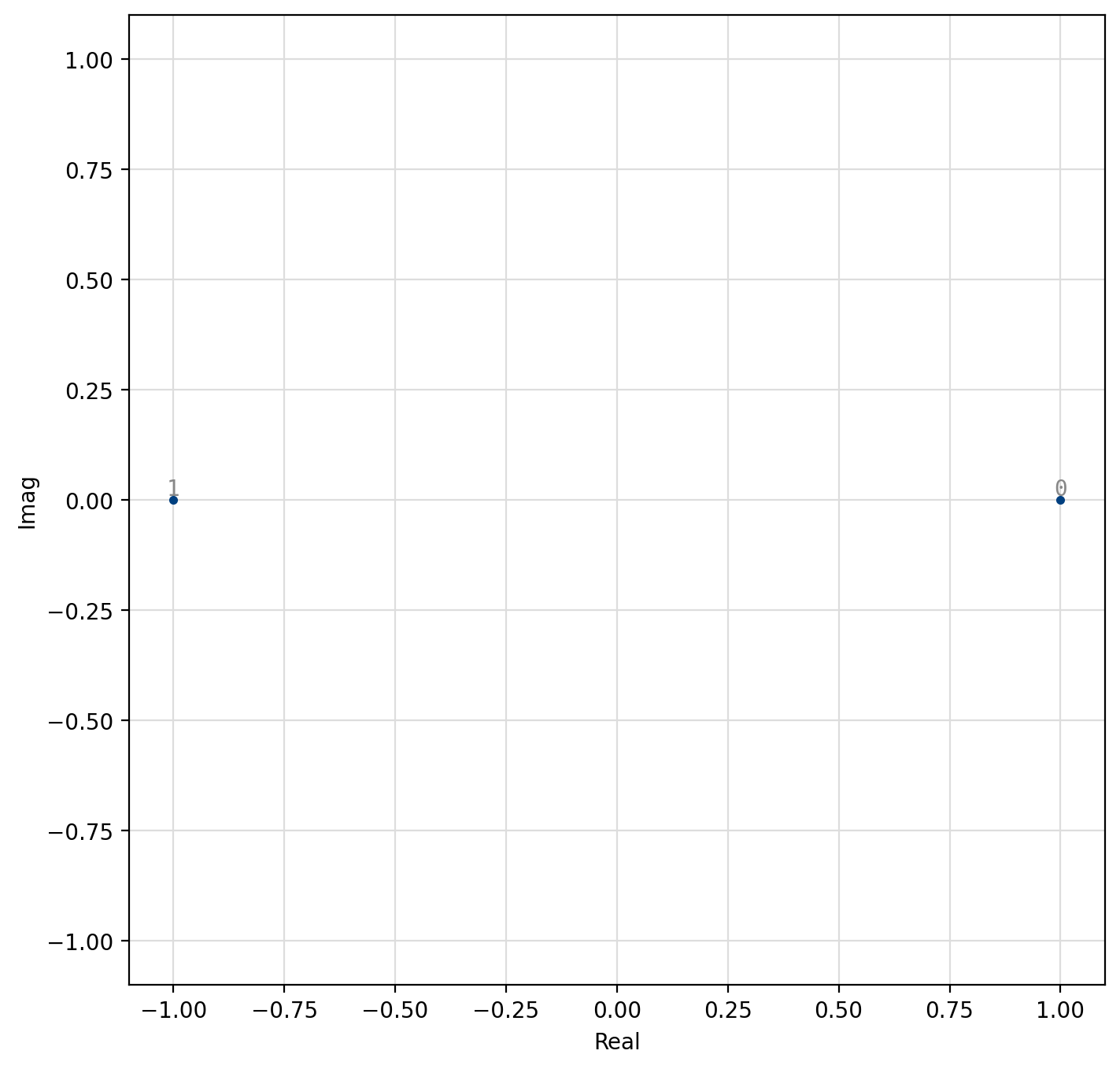
Figure 29 2-PSK (generic BPSK)

Figure 30 4-PSK (generic QPSK)
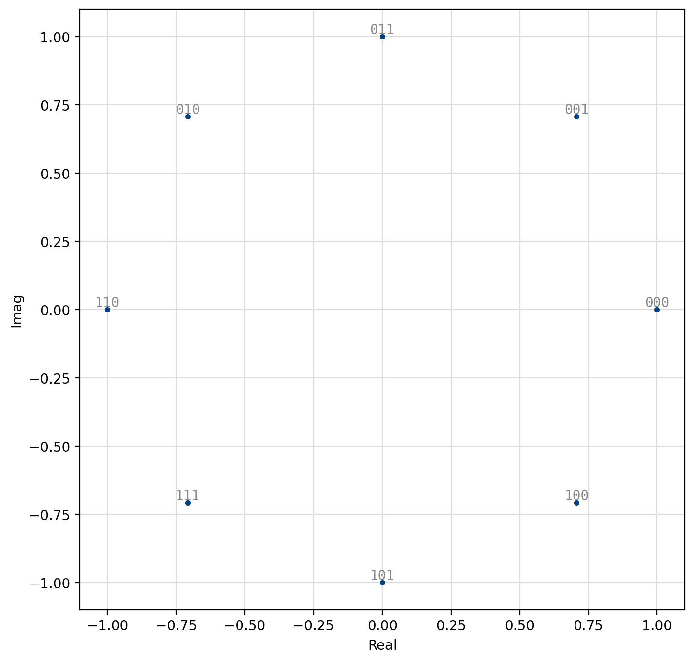
Figure 31 8-PSK
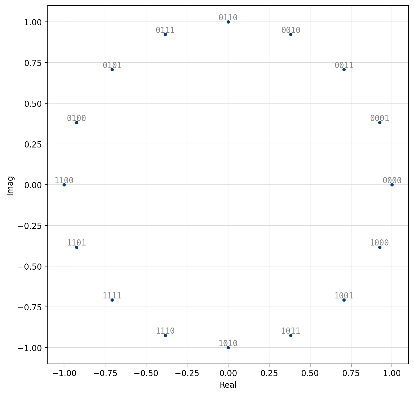
Figure 32 16-PSK
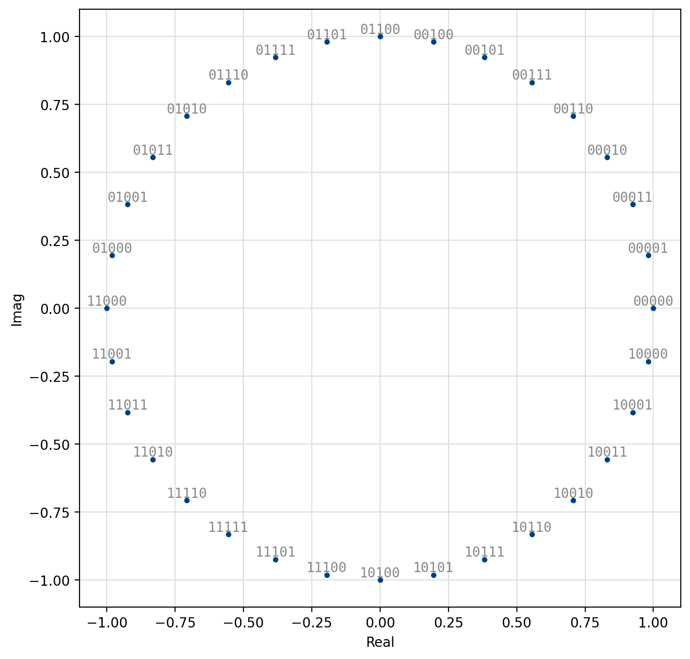
Figure 33 32-PSK
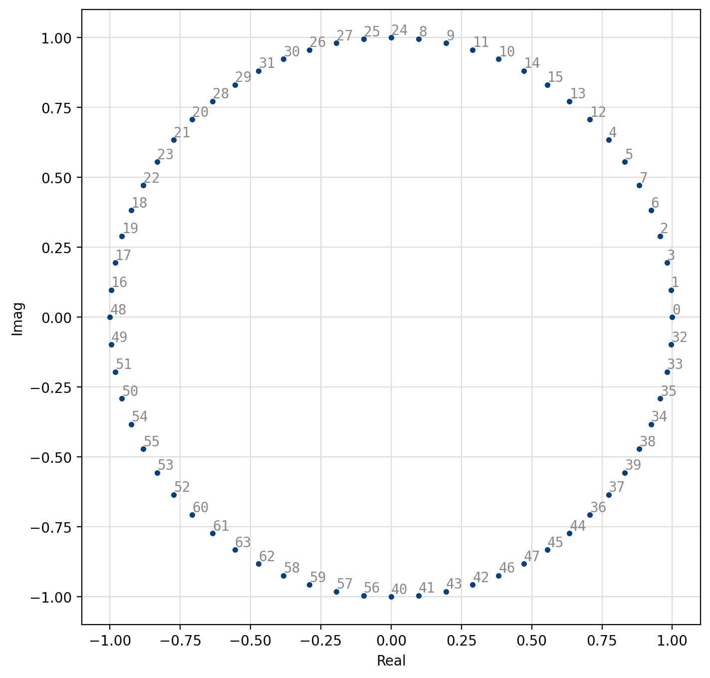
Figure 34 64-PSK
[fig-modem-psk] depicts the constellation of PSK up to \(M=16\)
with the bits gray encoded.
While liquid-dsp supports up to \(M=256\), values greater than \(M=32\)
are typically avoided due to error rates for practical signal-to-noise
ratios.
For an \(M\)-symbol constellation, the \(k^{th}\) symbol is
where \(k \in \{0,1,\ldots,M-1\}\). Specific schemes include BPSK (\(M=2\)),
and QPSK (\(M=4\))
Demodulation is performed independent of the signal amplitude for coherent PSK.
Differential Phase-shift Keying (DPSK)
Differential PSK (DPSK) encodes information in the phase change of the carrier. Like regular PSK demodulation is performed independent of the signal amplitude; however because the data are encoded using phase transitions rather than absolute phase, the receiver does not have to know the absolute phase of the transmitter. This allows the receiver to demodulate incoherently, but at a quality degradation of 3dB. As such the \(n^{th}\) transmitted symbol \(k(n)\) depends on the previous symbol, viz
Amplitude/Phase-shift Keying (APSK)
Amplitude/phase-shift keying (APSK) is a specific form of quadrature amplitude modulation where constellation points lie on concentric circles. The constellation points are further apart than those of PSK/DPSK, resulting in an improved error performance. Furthermore the phase recovery for APSK is improved over regular QAM as the constellation points are less sensitive to phase noise. This improvement comes at the cost of an increased computational complexity at the receiver. Demodulation follows as a two-step process: first, the amplitude of the received signal is evaluated to determine in which level (“ring”) the transmitted symbol lies. Once the level is determined, the appropriate symbol is chosen based on its phase, similar to PSK demodulation. Demodulation of APSK consumes slightly more clock cycles than the PSK and QAM demodulators.
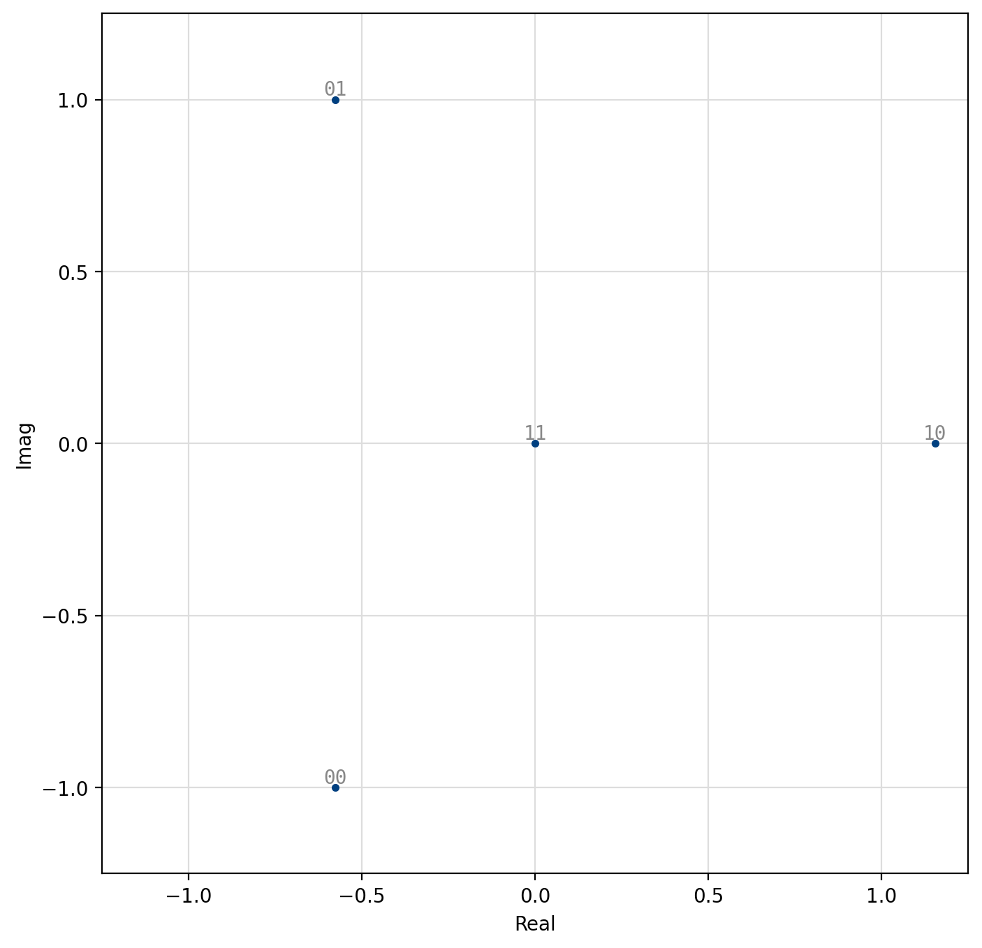
Figure 35 4-APSK (1,3)
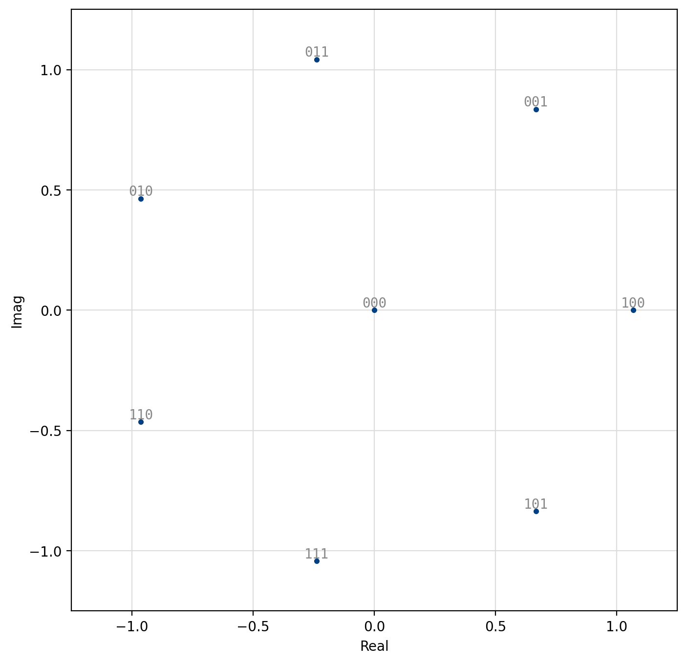
Figure 36 8-PSK (1,7)
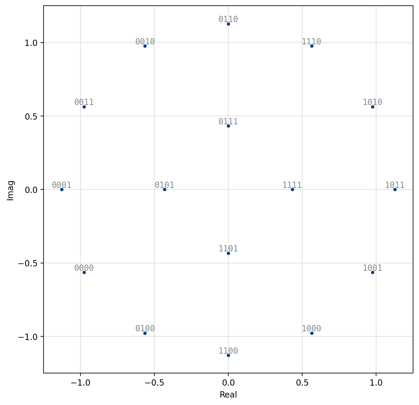
Figure 37 16-APSK (4,12)
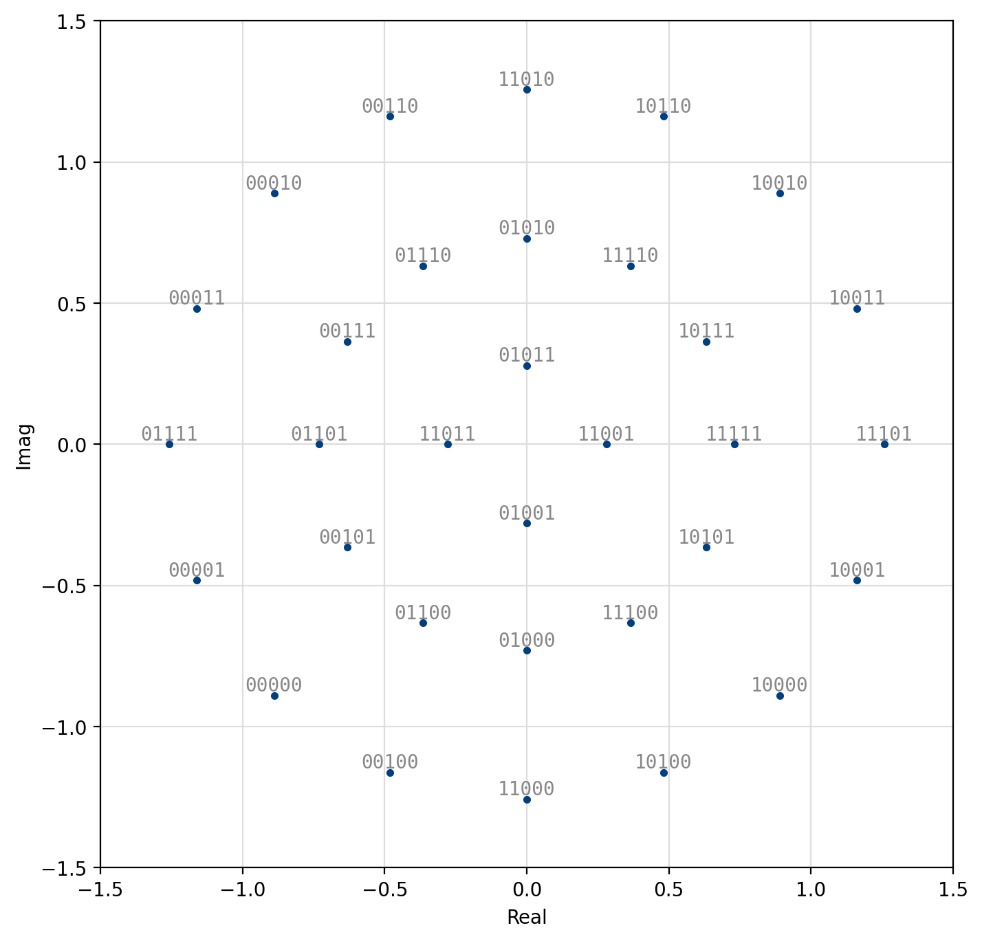
Figure 38 32-APSK (4,12,16)
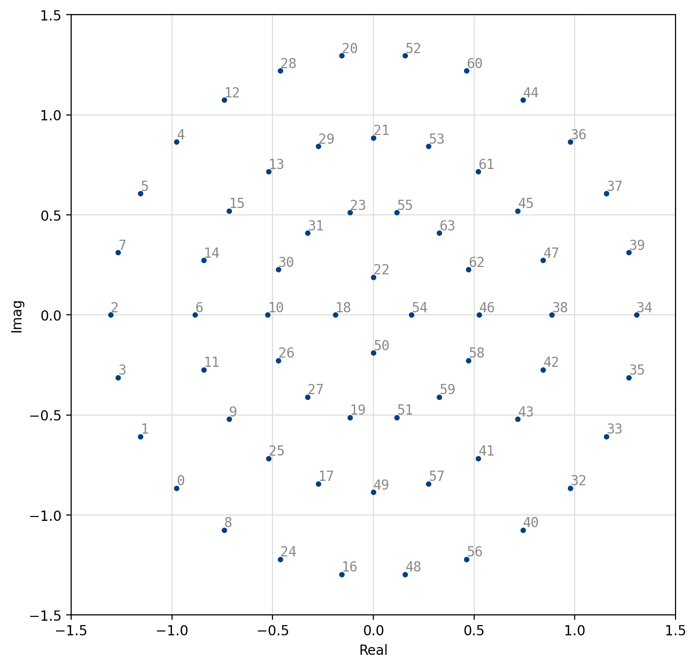
Figure 39 64-APSK (4,14,20,26)
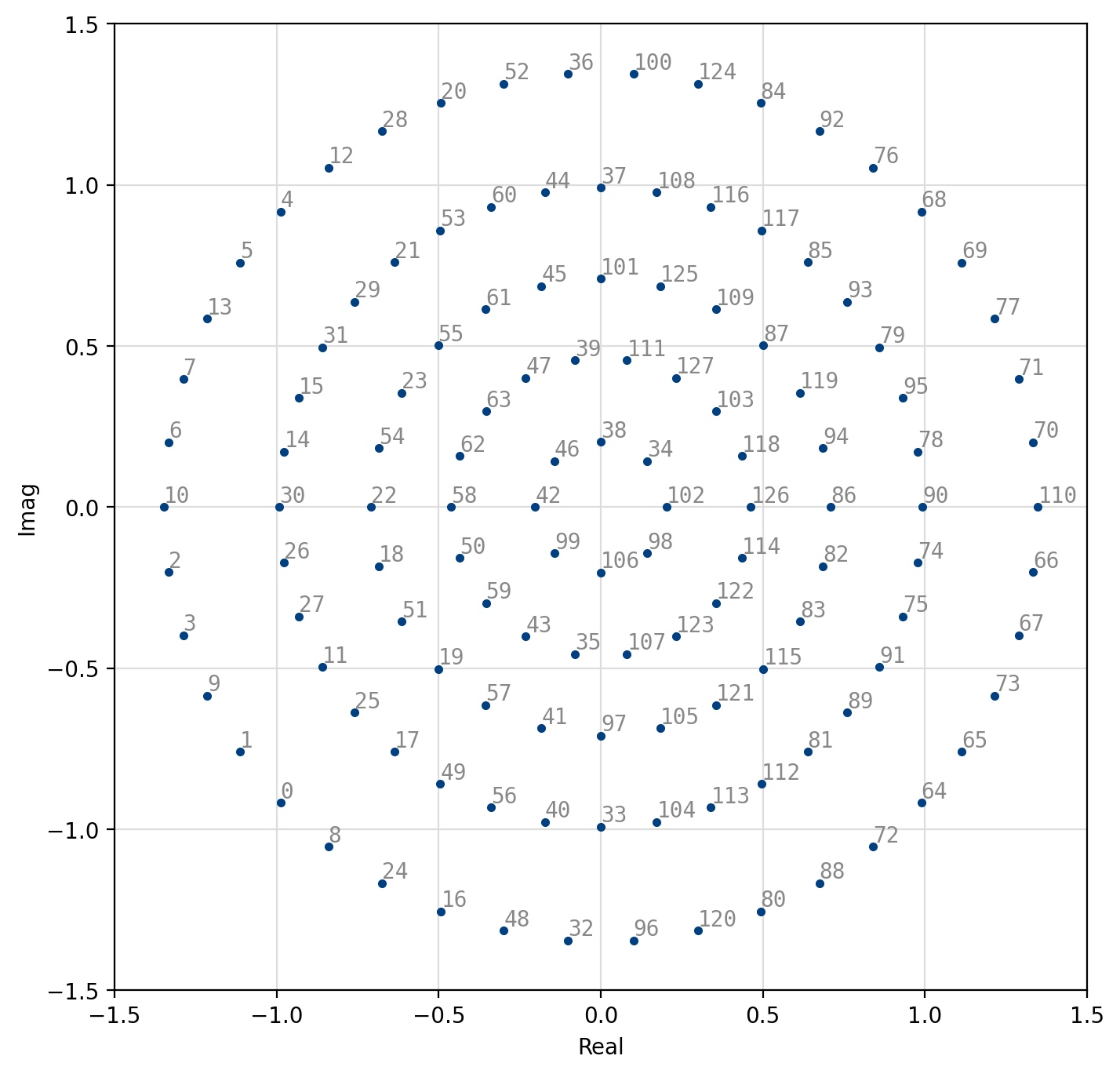
Figure 40 128-APSK (8,18,24,36,42)
[fig-modem-apsk] depicts the available APSK signal constellations for \(M\) up to 128. The constellation points and bit mappings have been optimized to minimize the bit error rate in 10 dB SNR.
Amplitude-shift Keying (ASK)
Amplitude-shift keying (ASK) is a simple form of amplitude modulation by which the information is encoded entirely in the in-phase component of the baseband signal. The encoded symbol is simply
where \(\alpha\) is a scaling factor to ensure \(E\{s_k^2\}=1\),
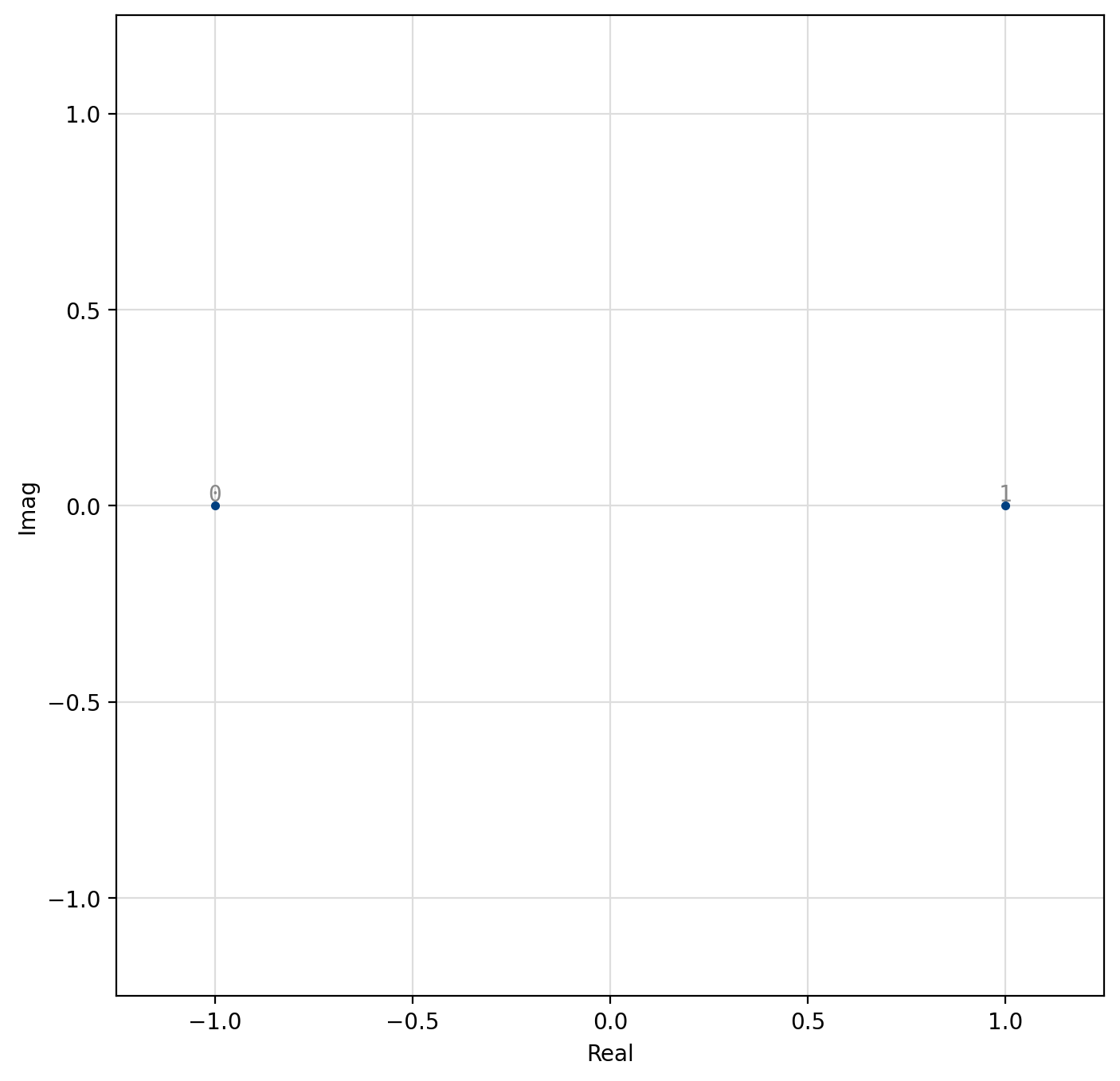
Figure 41 2-ASK
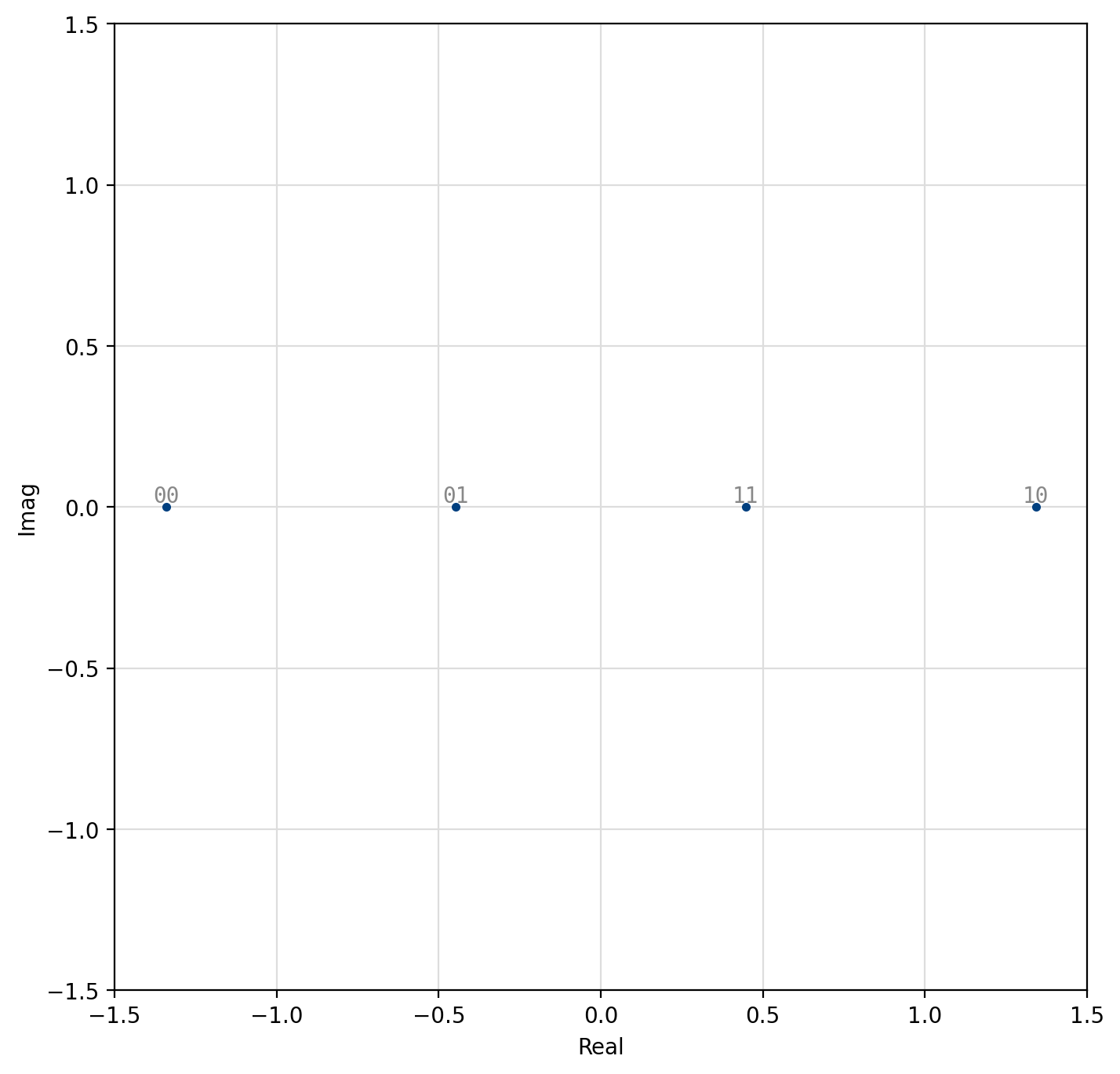
Figure 42 4-ASK
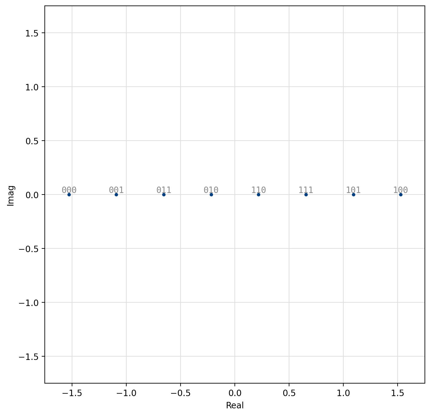
Figure 43 8-ASK
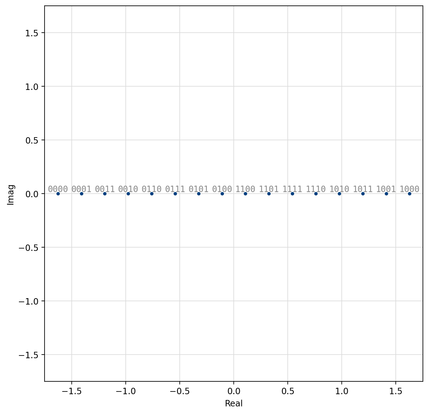
Figure 44 16-ASK
[fig-modem-ask] depicts the ASK constellation map for \(M\) up to 16. Due to the poor error rate performance of ASK values of \(M\) greater than 16 are not recommended.
Quadrature Amplitude Modulation (QAM)
Also known as quadrature amplitude-shift keying, QAM modems encode data using both the in-phase and quadrature components of a signal amplitude. In fact, the symbol is split into independent in-phase and quadrature symbols which are encoded separately as LIQUID_MODEM_ASK symbols. Gray encoding is applied to both the I and Q symbols separately to help ensure minimal bit changes between adjacent samples across both in-phase and quadrature-phase dimensions. This is made evident in [fig-modem-qam-64] where one can see that the first three bits of the symbol encode the in-phase component of the sample, and the last three bits encode the quadrature component of the sample. We may formally describe the encoded sample is
where \(k_i\) is the in-phase symbol, \(k_q\) is the quadrature symbol, \(M_i = 2^{m_i}\) and \(M_q = 2^{m_q}\), are the number of respective in-phase and quadrature symbols, \(m_i=\lceil \log_2(M) \rceil\) and \(m_q=\lfloor \log_2(M) \rfloor\) are the number of respective in-phase and quadrature bits, and \(\alpha\) is a scaling factor to ensure \(E\{s_k^2\}=1\),
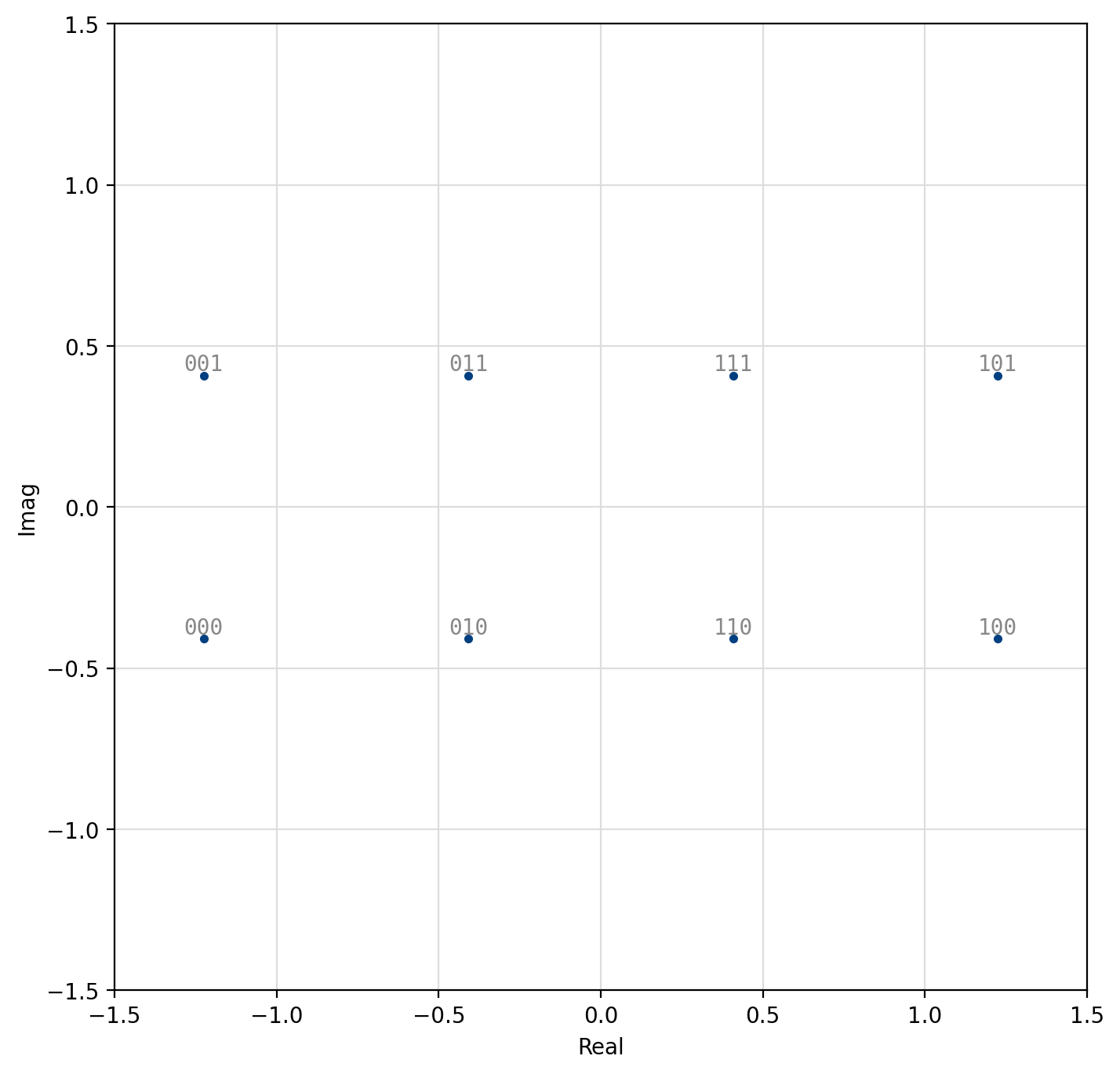
Figure 45 8-QAM constellation

Figure 46 16-QAM constellation
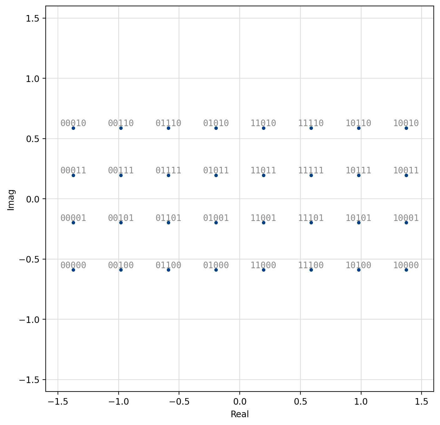
Figure 47 32-QAM constellation
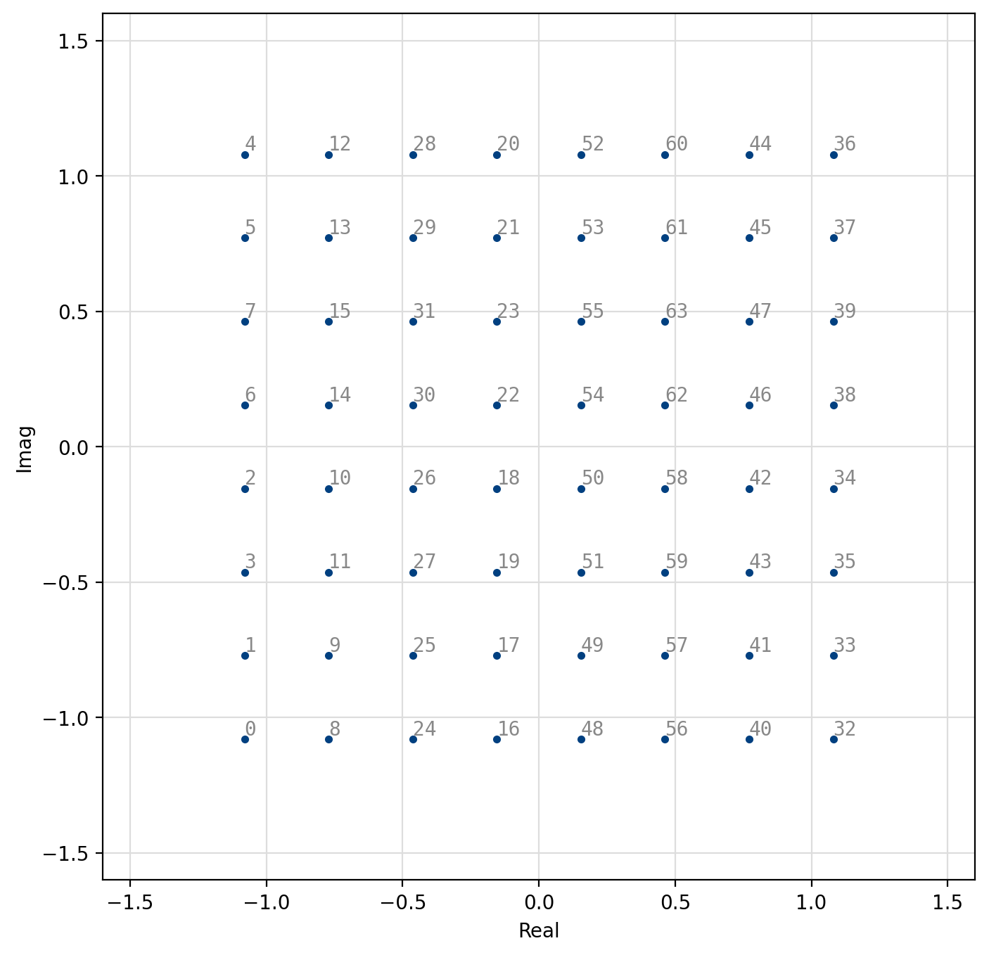
Figure 48 64-QAM constellation
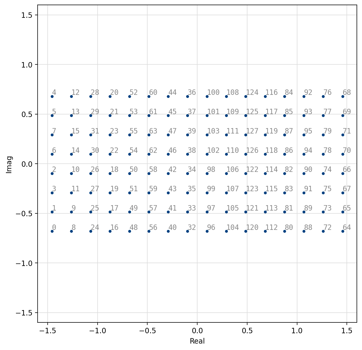
Figure 49 128-QAM constellation
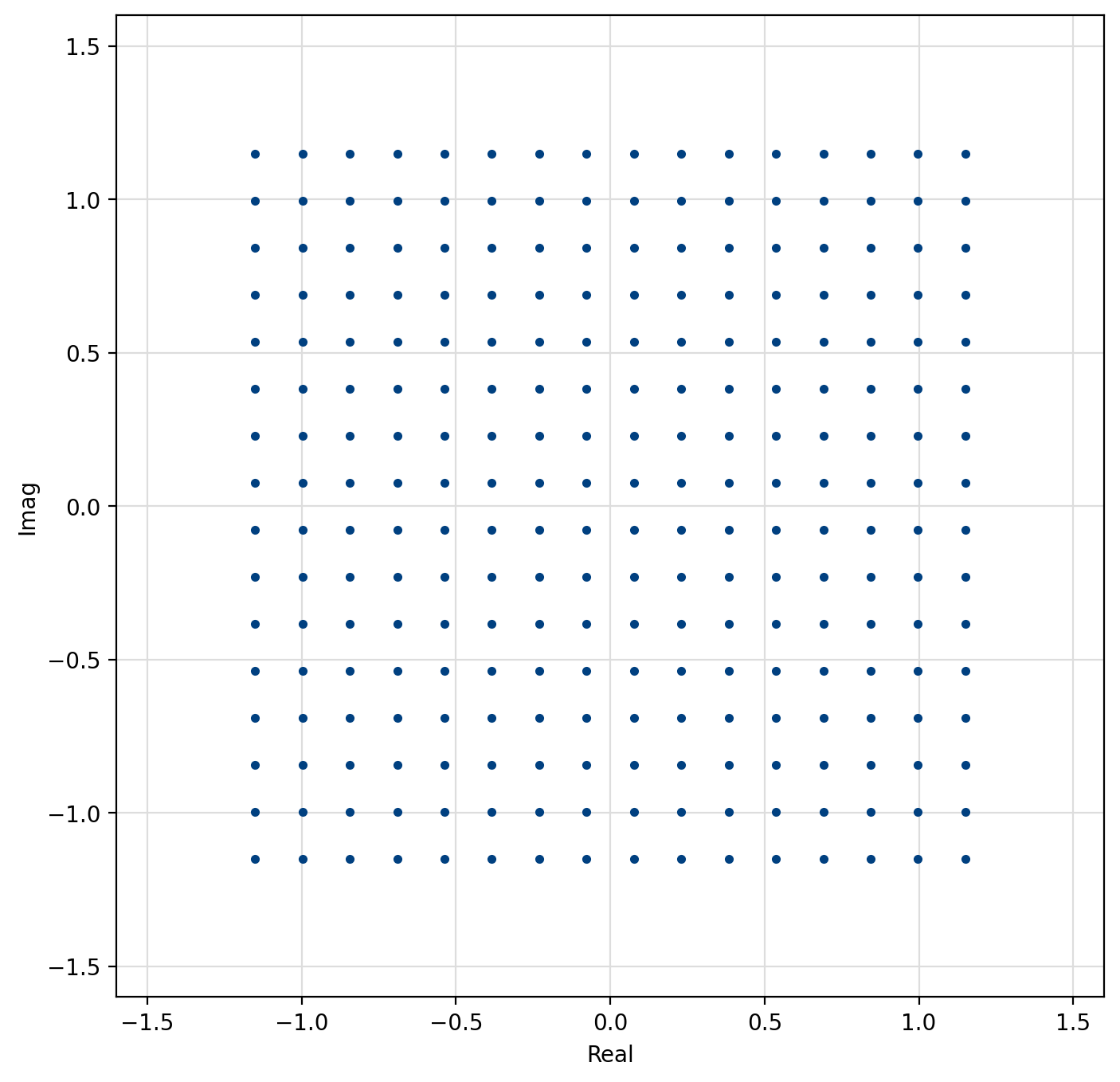
Figure 50 256-QAM constellation
[fig-modem-qam] depicts the arbitrary rectangular QAM modem constellation maps for \(M\) up to 256. Notice that all the symbol points are gray encoded to minimize bit errors between adjacent symbols.
Fixed-size Modulation Types
BPSK, QPSK, etc.
Arbitrary Modulation Types
liquid-dsp also allows the user to create their own modulation schemes by
designating the full signal constellation.
The penalty for defining a constellation as an arbitrary set of points
is that it cannot be decoded systematically.
All of the previous modulation schemes have the benefit of being very
fast to decode, and do not necessitate searching over the entire
constellation space to find the nearest symbol.
An example interface for generating a pair of arbitrary modems is listed
below.
Several pre-defined arbitrary signal constellations are available, including optimal QAM constellations, and some other fun (but perhaps not so useful) modulation schemes.
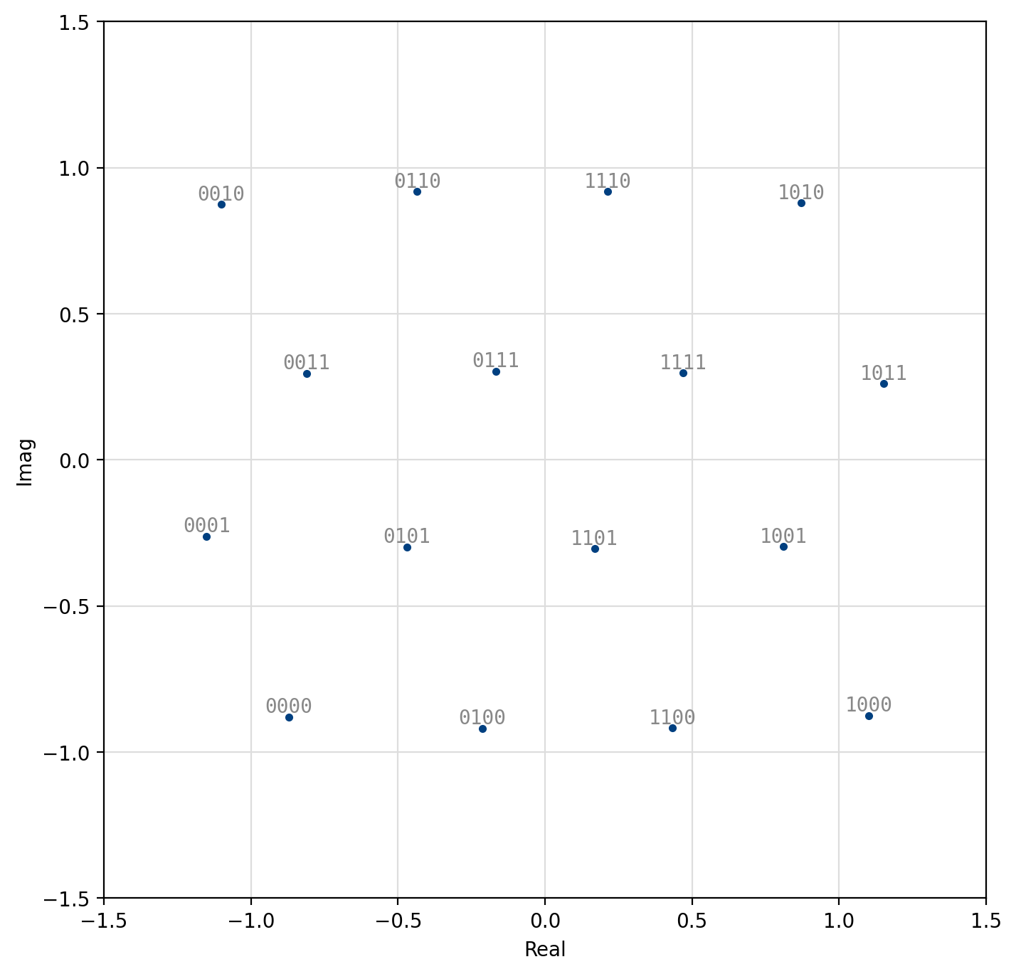
Figure 51 Optimal 16-QAM
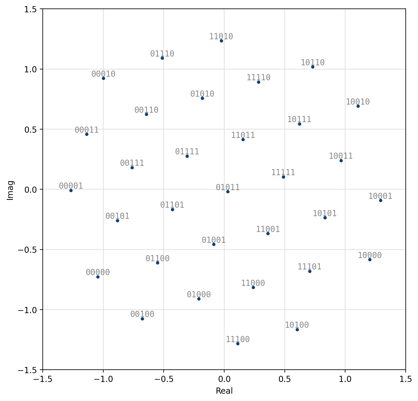
Figure 52 Optimal 32-QAM
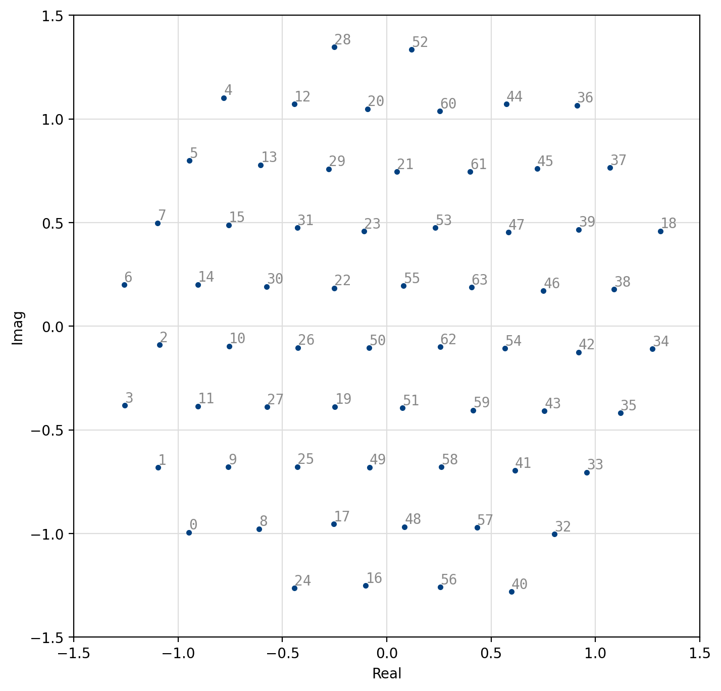
Figure 53 Optimal 64-QAM
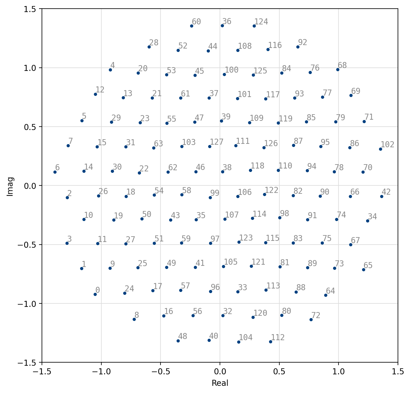
Figure 54 Optimal 128-QAM
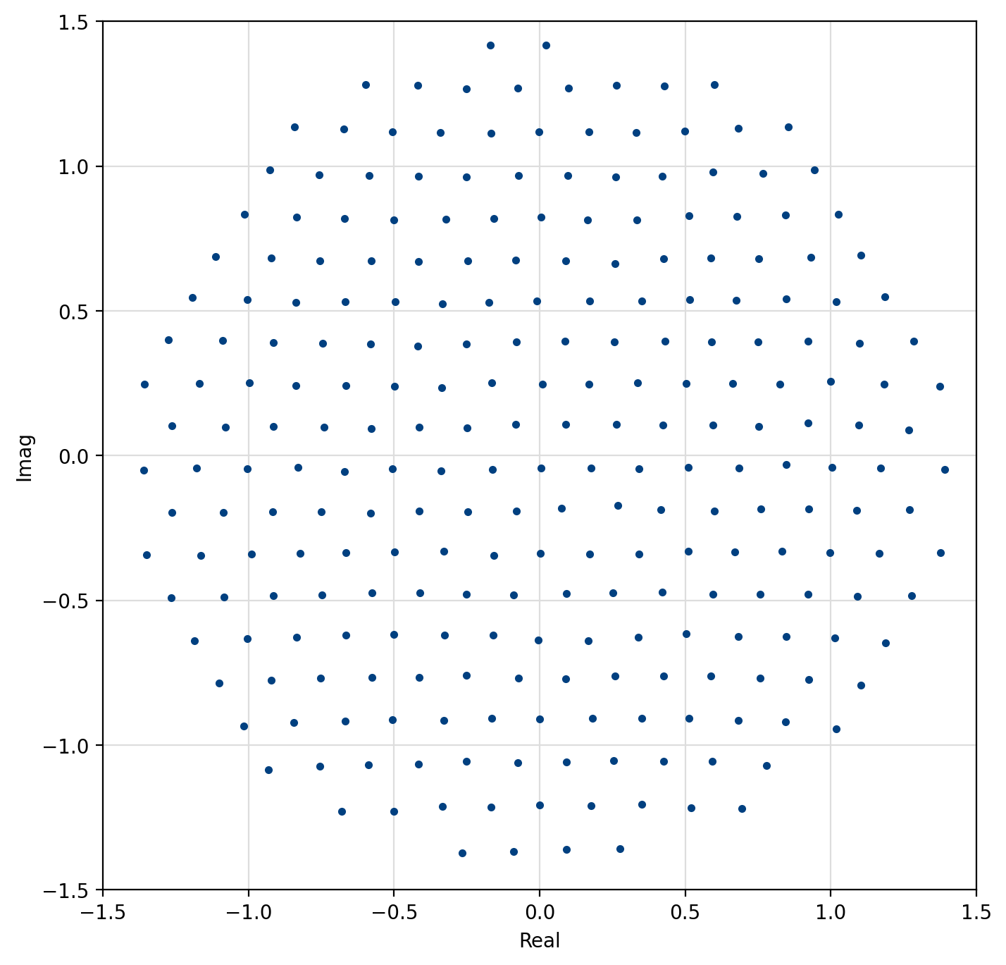
Figure 55 Optimal 256-QAM
[fig-modem-optqam] shows the constellation maps for the optimal QAM schemes. Notice that the constellations approximate a circle with each point falling on the lattice of equilateral triangles. Furthermore, adjacent constellation points differ by typically only a single bit to reduce the resulting bit error rate at the output of the demodulator. These constellations marginally out-perform regular square QAM (see Figures [fig-modem-M32] and [fig-modem-M128]) at the expense of a significantly increased computational complexity.
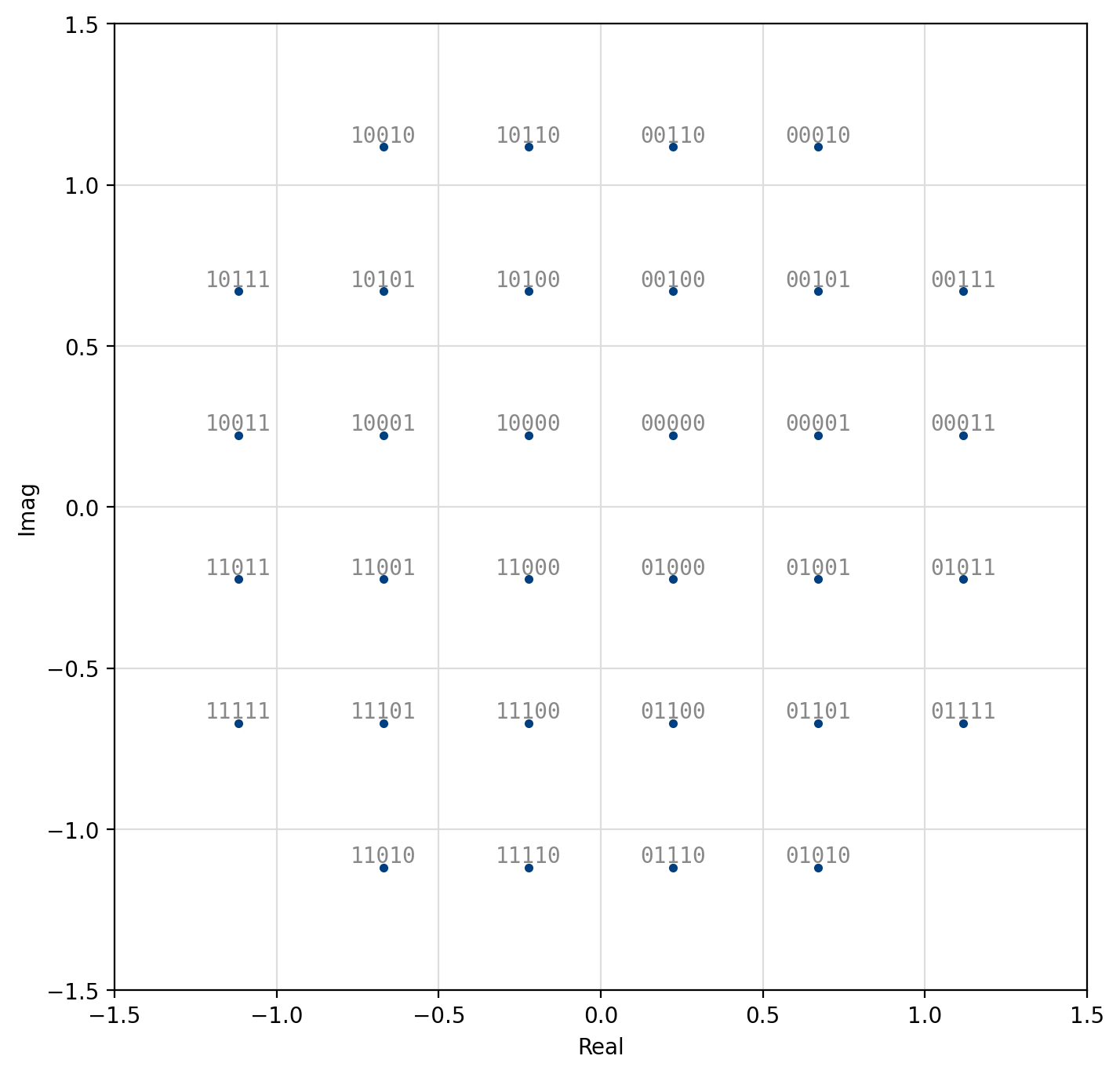
Figure 56 “Square” 32-QAM
Figure 57 “Square” 128-QAM
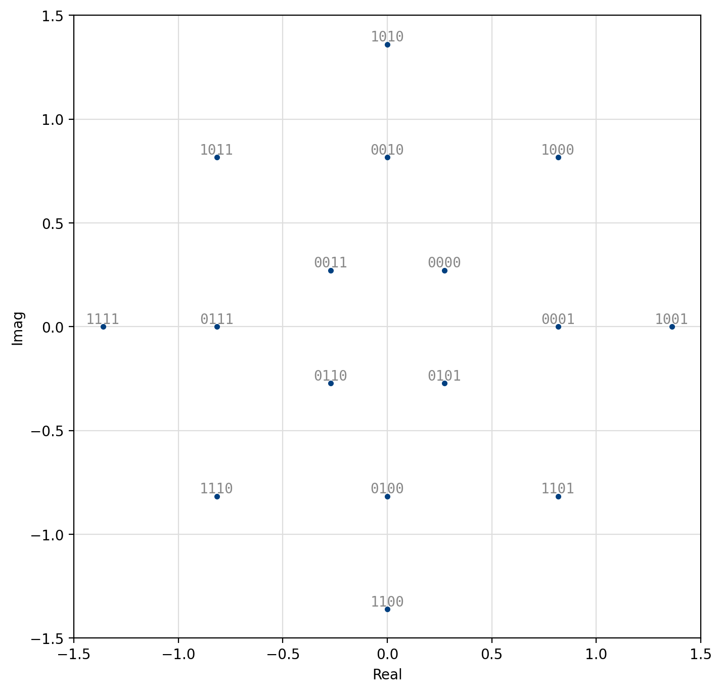
Figure 58 V.29
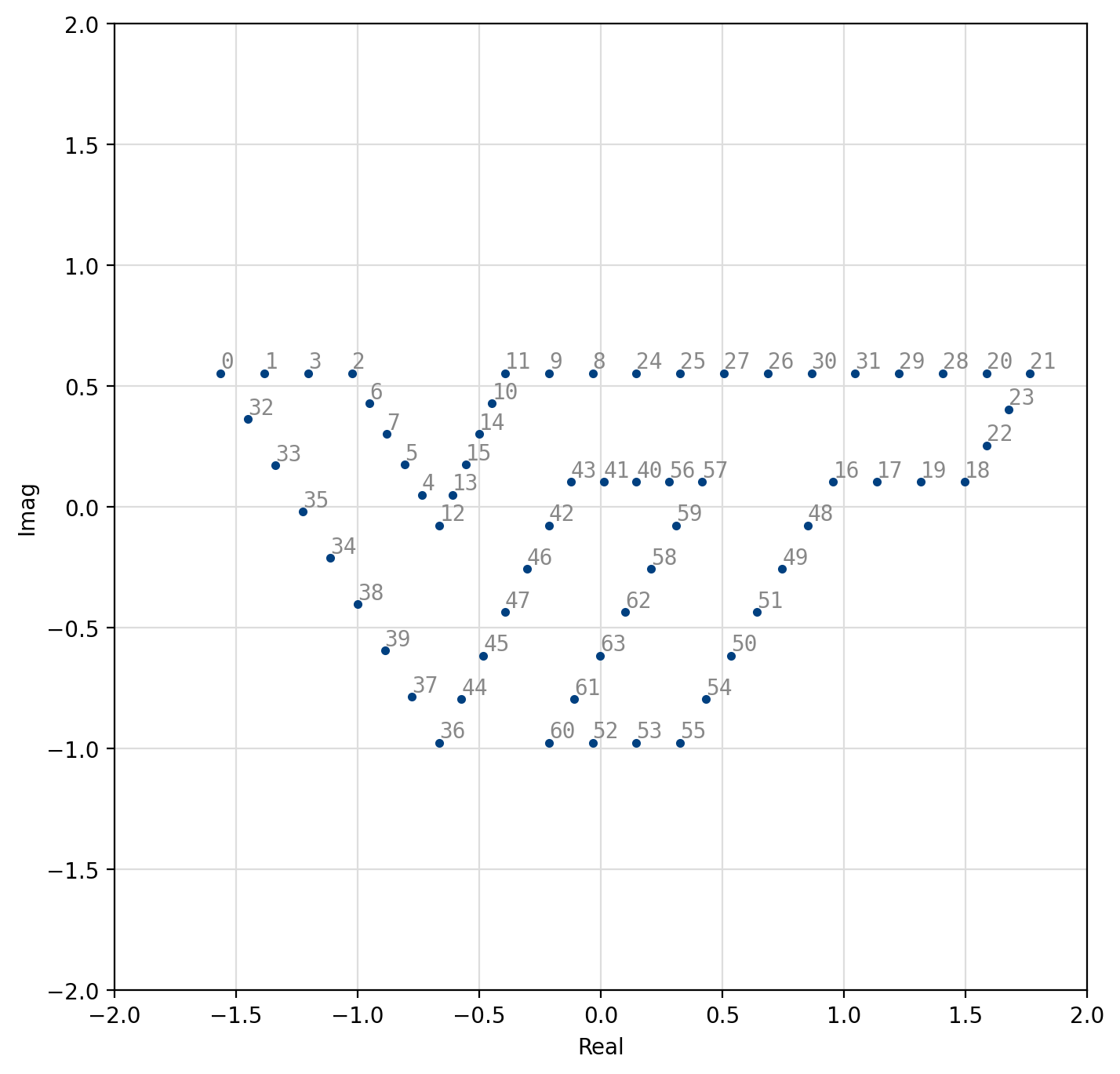
Figure 59 Arbitrary 64-QAM VT
[fig-modem-arb] depicts several available arbitrary constellation maps; however the user can create any arbitrary constellation map so long as no two points overlap (see modem_arb_init() and modem_arb_init_file() in [section-modem-digital-interface]).
Interface
While the same modem structure may be used for both modulation and
demodulation for most schemes, it is important to use separate objects
for differential-mode modems (e.g. LIQUID_MODEM_DPSK) as the internal state
will change after each symbol.
It is usually good practice to keep separate instances of modulators and
demodulators.
This holds true for most any encoder/decoder pair in liquid-dsp.
An example of the modem interface is listed below.
Listed below is the full interface to the modem family of
objects.
create()
Create digital modem object with a particular scheme
modemcf = modemcf_create(modulation_scheme _scheme);
modulation_scheme _scheme: linear modulation scheme (e.g. LIQUID_MODEM_QPSK)returns new
modemcfobject
modem = modem_create(modulation_scheme _scheme);
modulation_scheme _scheme: linear modulation scheme (e.g. LIQUID_MODEM_QPSK)returns new
modemobject
create_arbitrary()
Create linear digital modem object with arbitrary constellation points defined by an external table of symbols. Sample points are provided as complex float pairs and converted internally if needed.
modemcf = modemcf_create_arbitrary(liquid_float_complex * _table, unsigned int _M);
liquid_float_complex * _table: array of complex constellation pointsunsigned int _M: modulation order and table sizereturns new
modemcfobject
modem = modem_create_arbitrary(liquid_float_complex * _table, unsigned int _M);
liquid_float_complex * _table: array of complex constellation pointsunsigned int _M: modulation order and table sizereturns new
modemobject
recreate()
Recreate modulation scheme, re-allocating memory as necessary
modemcf = modemcf_recreate(modemcf _q, modulation_scheme _scheme);
modemcf _q: modem objectmodulation_scheme _scheme: linear modulation scheme (e.g. LIQUID_MODEM_QPSK)returns new
modemcfobject
modem = modem_recreate(modem _q, modulation_scheme _scheme);
modem _q: modem objectmodulation_scheme _scheme: linear modulation scheme (e.g. LIQUID_MODEM_QPSK)returns new
modemobject
copy()
Copy object including all internal objects and state
modemcf = modemcf_copy(modemcf _q);
modemcf _q:returns new
modemcfobject
modem = modem_copy(modem _q);
modem _q:returns new
modemobject
destroy()
Destroy modem object, freeing all allocated memory
int = modemcf_destroy(modemcf _q);
modemcf _q:returns standard error code
int = modem_destroy(modem _q);
modem _q:returns standard error code
print()
Print modem status to stdout
int = modemcf_print(modemcf _q);
modemcf _q:returns standard error code
int = modem_print(modem _q);
modem _q:returns standard error code
reset()
Reset internal state of modem object; note that this is only relevant for modulation types that retain an internal state such as LIQUID_MODEM_DPSK4 as most linear modulation types are stateless
int = modemcf_reset(modemcf _q);
modemcf _q:returns standard error code
int = modem_reset(modem _q);
modem _q:returns standard error code
gen_rand_sym()
Generate random symbol for modulation
unsigned int = modemcf_gen_rand_sym(modemcf _q);
modemcf _q:returns something good
unsigned int = modem_gen_rand_sym(modem _q);
modem _q:returns something good
get_bps()
Get number of bits per symbol (bps) of modem object
unsigned int = modemcf_get_bps(modemcf _q);
modemcf _q:returns something good
unsigned int = modem_get_bps(modem _q);
modem _q:returns something good
get_scheme()
Get modulation scheme of modem object
modulation_scheme = modemcf_get_scheme(modemcf _q);
modemcf _q:returns something good
modulation_scheme = modem_get_scheme(modem _q);
modem _q:returns something good
modulate()
Modulate input symbol (bits) and generate output complex sample
int = modemcf_modulate(modemcf _q, unsigned int _s, float complex * _y);
modemcf _q: modem objectunsigned int _s: input symbolfloat complex * _y: output complex samplereturns standard error code
int = modem_modulate(modem _q, unsigned int _s, float complex * _y);
modem _q: modem objectunsigned int _s: input symbolfloat complex * _y: output complex samplereturns standard error code
demodulate()
Demodulate input sample and provide maximum-likelihood estimate of symbol that would have generated it. The output is a hard decision value on the input sample. This is performed efficiently by taking advantage of symmetry on most modulation types. For example, square and rectangular quadrature amplitude modulation with gray coding can use a bisection search independently on its in-phase and quadrature channels. Arbitrary modulation schemes are relatively slow, however, for large modulation types as the demodulator must compute the distance between the received sample and all possible symbols to derive the optimal symbol.
int = modemcf_demodulate(modemcf _q, float complex _x, unsigned int * _s);
modemcf _q: modem objectfloat complex _x: input sampleunsigned int * _s: output hard symbolreturns standard error code
int = modem_demodulate(modem _q, float complex _x, unsigned int * _s);
modem _q: modem objectfloat complex _x: input sampleunsigned int * _s: output hard symbolreturns standard error code
demodulate_soft()
Demodulate input sample and provide (approximate) log-likelihood ratio (LLR, soft bits) as an output. Similarly to the hard-decision demodulation method, this is computed efficiently for most modulation types.
int = modemcf_demodulate_soft(modemcf _q, float complex _x, unsigned int * _s, unsigned char * _soft_bits);
modemcf _q: modem objectfloat complex _x: input sampleunsigned int * _s: output hard symbolunsigned char * _soft_bits: output soft bitsreturns standard error code
int = modem_demodulate_soft(modem _q, float complex _x, unsigned int * _s, unsigned char * _soft_bits);
modem _q: modem objectfloat complex _x: input sampleunsigned int * _s: output hard symbolunsigned char * _soft_bits: output soft bitsreturns standard error code
get_demodulator_sample()
Get demodulator’s estimated transmit sample
int = modemcf_get_demodulator_sample(modemcf _q, float complex * _x_hat);
modemcf _q:float complex * _x_hat:returns standard error code
int = modem_get_demodulator_sample(modem _q, float complex * _x_hat);
modem _q:float complex * _x_hat:returns standard error code
get_demodulator_phase_error()
Get demodulator phase error
float = modemcf_get_demodulator_phase_error(modemcf _q);
modemcf _q:returns something good
float = modem_get_demodulator_phase_error(modem _q);
modem _q:returns something good
get_demodulator_evm()
Get demodulator error vector magnitude
float = modemcf_get_demodulator_evm(modemcf _q);
modemcf _q:returns something good
float = modem_get_demodulator_evm(modem _q);
modem _q:returns something good